
When clothes being worn a long time ,due to friction so that the yarn thinning, the fabric within the local yarn stress breakage and the formation of cracks, used as military uniforms, puff sails, parachutes, hammocks and other fabrics, in use more vulnerable to the role of concentrated load, so that the products are locally damaged and rupture, the fabric is hooked by the object, or the fabric is held locally, under the action of external forces so that the fabric is torn in half, the fabric is subject to such The phenomenon of being torn under the action of concentrated load, usually called tearing.
Fabric tear strength is an important indicator of textiles, the determination of this indicator using the instrument called fabric tear tester, also called Elmendorf (Elmendorf) type fabric tear tester, fabric tear tester can be used for a variety of fabric tear strength determination.
Principle of Elmendorf Tear Test
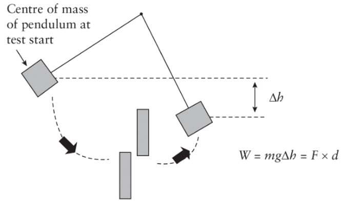
It is measured by measuring the pendulum at a certain starting height to fall, all the potential energy into kinetic energy and then through the reduction of its potential energy converted into the work used to tear the fabric specimen, and then according to the original length of the textile sample to calculate the average tearing force. It is also called the Elmendorf tear strength.
Elmendorf Tear Test Method(refer to ASTM D 1424)
1.Scope.
1.1 This test method is used to determine the force value required to tear a fabric in a single pass with a Elmendorf Tearing Tester or falling hammer type instrument.
1.2 This test method is applicable to most fabrics, including woven, layered fleece, fleece, blanket and air bag fabrics, provided that the fabric does not tear in a direction that crosses the direction of the applied force during the test. Fabrics may be untreated, oversized, coated, resin-treated, or otherwise treated. Precautions for testing specimens with or without wetting are described later, respectively.
1.3 This test method is suitable only for the warp direction tests of warp-knit fabrics. It is not suited for the course direction of warp knit fabrics or either direction of most other knitted fabrics.
1.4 This test method is primarily based on values expressed in international units or U.S. customary units, but each of the two must be used separately. U.S. customary units are more appropriate.
1.5 This standard does not address all safety issues. It is the responsibility of the user of this standard to establish appropriate safety and health practices and to determine the applicability of regulatory limits prior to use.
- Referenced Documents
ASTM Standards:2
D 123 Terminology Relating to Textiles
D 629 Test Methods for Quantitative Analysis of Textiles
D 1776 Practice for Conditioning and Testing Textiles
D 2261 Test Method for Tearing Strength of Fabrics by the Tongue (Single Rip) Procedure (Constant-Rate-of Extension Tensile Testing Machine)
D 2904 Practice for Inter laboratory Testing of a Textile Test Method that Produces Normally Distributed Data
D 2906 Practice for Statements on Precision and Bias for Textiles3
D 4848 Terminology Related to Force, Deformation and Related Properties of Textiles
D 4850 Terminology Relating to Fabrics and Fabric Test Methods
D 5587 Test Method for Tearing Strength of Fabrics by Trapezoid Procedure
- Terminology
3.1 For all terms related to D13.59, Test Methods for Textiles, General, refer to Terminology D 4850.
3.2 For all terms related to force, deformation and related properties of textiles, refer to term D 4848.
3.2.1 The following terms are relevant to this standard: cross machine direction, CD, tear length, machine direction, MD, tear energy, tear force, tear resistance, tear strength, fabric.
3.3 For all other terms related to textiles, please refer to the term D 123.
- Overview of the test method
A gap is centrally reserved in the specimen between the two clamps, the specimen is torn a fixed distance and the tearing resistance is partially accounted for in the scale reading of the instrument and the test result will be calculated from this reading and the pendulum capacity.
- Significance and use
5.1 This test method is an acceptance test for the determination of tear strength using a falling hammer apparatus for fabrics, but caution is advised, as the technician may not obtain good results on some fabrics. Comparative tests may be required in accordance with the instructions in 5.1.1.
5.1.1 In the event of a dispute over differing reported test results when acceptance testing commercial shipments using this test method, purchasers and suppliers should perform comparative testing to determine if statistical deviations exist between their laboratories. Statistical assistance for investigating bias is recommended. At a minimum, both parties should take a set of test samples that are as homogeneous as possible, and these samples should be from a batch of fabrics of the relevant type. These test samples should then be randomly assigned to each laboratory in equal numbers for testing. The average results of the two laboratories should be compared using appropriate statistical analysis and an acceptable level of probability selected by both parties prior to the start of the test. If deviations are found, their causes must be found and corrected, or the purchaser and supplier must agree to take known deviations into account when interpreting future test results.
5.2 Microprocessor systems for automated data collection can provide economical and reliable results when properly calibrated. See Test Methods D 2261 and D 5587.
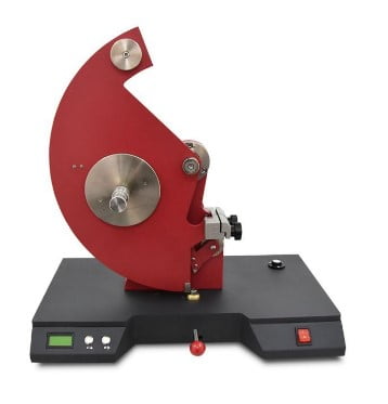
6.Instruments
6.1 Falling Hammer (Elmendorf type) Tester
-The tester consists of: a fixed clamp, a clamp on a pendulum that can swing freely on bearings, the applicable leveling device, a device to hold the pendulum in an elevated position, a device for instant release of the pendulum, and a device for measuring the force of tearing the specimen.
6.1.1 A knife can be mounted on a fixed post for making the initial cut in the specimen, centered between the fixtures, and adjusted in height so that the tearing distance is 43.0 6 0.15 mm (1.69 6 0.005 in. That is, when the lower edge of a 63.0 mm (2.5 6 0.005 in.) wide specimen rests against the bottom of the fixture, the distance between the end of the knife cut and the upper edge of the specimen is 43.0 6 0.15 mm (1.69 6 0.005 in.).
6.1.2 When the pendulum is in its initial position ready for testing, the distance between the two clamps is 2.5 6 0.25 mm (0.1 6 0.01 in.) and is aligned so that the clamped specimen lies in a plane parallel to the axis of the pendulum, which is at an angle of 0.480 rad (27.5 6 0.5°) to the vertical line joining the axis and the horizontal line formed by the upper edge of the clamp. The distance between the axis and the upper edge of the clamp is 1036 0.1 mm (4.055 6 0.004 in.). The clamping surface of each jaw is at least 25 mm (1.0 in.) wide and 15.9 6 0.1 mm (0.625 6 0.004 in.) deep.
6.1.3 The Elmendorf Tearing Tester may have a pointer mounted on the same axis as the pendulum to record the tearing force, or it may be replaced by other methods of calculating and displaying, such as a digital display and a computer-driven system. Air-driven clamps are preferred, but manual clamps are also allowed.
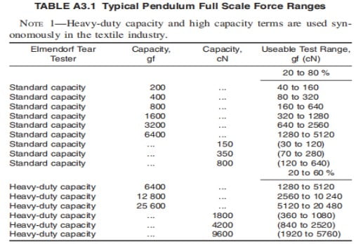
6.1.4 The Elmendorf Tearing Tester should be capable of providing interchangeable full scale force ranges. Typical full scale ranges are shown in Table A3.1.
6.2 Calibration weights for calibrating 50% of the full scale force range, or other method as described by the Elmendorf Tearing Tester manufacturer.
6.3 Cutting dies may have the shape and dimensions shown in Figure 1 (a) or (b). Both dies can provide a basic rectangular specimen 100 6 2 mm (4 6 0.05 in.) long by 63 6 0.15 mm (2.5 6 0.005 in.) wide, with additional fabric at the top edge of the specimen to ensure that the bottom portion of the specimen is torn during testing. The critical dimension of the specimen is the distance of 43.0 6 0.15 mm (1.696 0.005 in.) to be torn during the test.
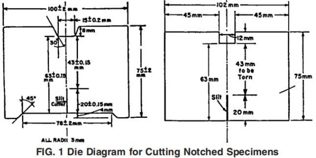
Note 1-The modified mold model shown in Figure 1(a) has two new features not found in the original model (Figure 1(b)), that is ,a cutout at the bottom of the specimen to help center the specimen in the fixture and (optionally) a provision for cutting a 20.0 mm (0.75 in.) slit before inserting the specimen into the tester. These dies can be ordered.
6.4 Air pressure regulator, capable of controlling air pressure between 410 kPa and 620 kPa (60 psi and 90 psi), where applicable, for air clamping.
6.5 Cutting blade setting gauge, capable of leaving a cutting gap of 43 6 0.15 mm (1.69 6 0.005 in.) for specimens 63 6 0.15 mm (2.5 6 0.005 in.) wide, or equivalent.
6.6 Jaw spacing gage 2.5 6 0.25 mm (0.1 6 0.01 in.) wide, or equivalent.
6.7 Oil, light weight, non-gummed clock type.
6.8 Silicone grease, when applicable, for air clamp lubrication.
6.9 Vacuum Cleaner, when applicable, for cleaning dust and fiber from sensor, or equivalent.
- Sampling and Test Samples
7.1 Bulk Samples – Bulk samples for acceptance testing shall be randomly selected from the number of rolls or pieces of cloth specified in the applicable material specification or other agreement between the buyer and seller. Consider these rolls or pieces of fabric as the primary sampling unit. In the absence of such an agreement, the number of rolls or pieces of cloth as specified in Table 1.
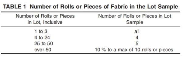
NOTE 2-The buyer and seller are to consider the variability between samples taken from the fabric to provide a sampling plan with meaningful producer risk, consumer risk, acceptable quality levels, and restricted quality levels.
7.2 Sample – from each roll or piece of fabric in the bulk sample to take a piece of the sample extending to the width of the fabric and about 1 meter (1 yard) along the machine direction. For rolls of fabric, the outer wrap of the roll or the inner wrap of the roll core of the fabric should not be used as a test sample.
7.3 Test Samples – Take 5 samples from each laboratory sampling unit in the machine direction and 5 samples across the machine direction for each of the test conditions described in 9.1 and 9.2.
7.3.1 Test Direction – Consider the long direction of the specimen as the test direction.
7.3.2 Cutting test specimens – Ensure that the longer dimension of the specimen used to measure the machine direction is parallel to the machine direction. Use the cutting die described in 6.3 and shown in Figure 1(a) or (b), as appropriate, for measuring specimens in the cross machine direction. When the specimen is to be tested wet, cut from the area adjacent to the dry test specimen. Label them to make the distinction.
7.3.2.1 When cutting woven fabric specimens, take care to align the yarns in the short direction parallel to the die so that when slits are cut, subsequent tearing will occur between these yarns and not through them. This precaution is most important when testing bowed fabrics.
7.3.2.2 Cut the most representative specimen, preferably along the diagonal of the laboratory sample and not closer to the edge than one-tenth of its width. Ensure that the specimen is free of creases, folds, or wrinkles. Avoid getting oil, water, grease, etc. on the specimen during handling.
- Preparation of Apparatus and Calibration
8.1 Select test instrument force range, such that the tear occurs between 20 and 80 % or 20 and 60 % of the full-scale range as applicable.
NOTE 4—For standard test apparatus, the useable portion of the full scale force range is 20 to 80 %. For the high capacity test instrument, the useable portion of the full scale force range is 20 to 60 %.
8.2 When equipped with a registering sensor, examine the scale and the complementary sensor. Using care and without touching the sensor, vacuum away any loose fibers and dust.
8.3 Check the cutter for sharpness, wear and center alignment.
8.4 For air clamps, set the clamp air pressure to approximately 550 kPa (80 psi).
8.4.1 The maximum measurement pressure should not exceed 620 kPa (90 psi) and the minimum measurement pressure should not be less than 410 kPa (60 psi).
8.5 When using an automatic microprocessor data acquisition system, set the appropriate parameters in accordance with the Elmendorf Tearing Tester manufacturer’s instructions.
- Conditioning
9.1 Condition 1, Standard Test Conditions.
9.1.1 Unless otherwise specified in the material specification or contract order, the specimens shall be pretreated to approximate moisture equilibrium in the standard atmosphere for textile pretreatment specified in D 1776.
9.1.2 After pretreatment, the specimens shall be brought to moisture equilibrium in the standard atmosphere specified in Practice D 1776 for testing textiles or, if applicable, in the specific atmosphere in which the tests are to be performed, unless otherwise specified in the material specification or contract order.
9.2 Condition 2, Wet Specimen Test Conditions.
9.2.1 If a desizing treatment is specified prior to wet testing, a desizing treatment that does not affect the normal physical properties of the fabric shall be used as specified in Test Method D 629.
9.2.2 Submerge the specimen in a container of distilled or deionized water at ambient temperature until completely submerged .
9.2.2.1 The immersion time must be sufficient to wet the specimen, as evidenced by the lack of significant change in tearing force after a longer immersion time. For fabrics that are not easily wetted by water, such as those treated with water repellent or waterproof materials, a 0.1% solution of non-ionic wetting agent can be added to the water bath.
- Elmendorf Tearing Testing Procedures
10.1 Test conditioned specimens in the standard environment for testing textiles, i.e., 21 6 1°C (70 6 2°F) and 65 6 2% relative humidity, unless otherwise specified in the material specification or contract order.
10.2 Place the pendulum in the starting position and the force recording device in the zero force position.
10.3 For Tester-Slit Specimens:
10.3.1 Place the long side of the specimen centrally in the fixture with the bottom side carefully resting on the baffle and the top side parallel to the top of the fixture. Close the fixture and fix the specimen with approximately the same tension on both fixtures. The specimen should be placed freely with its upper area facing the pendulum to ensure a shearing action.
10.3.2 Use the built-in knife blade to cut a 20 mm (0.787 in.) slit in the specimen, extending from the bottom edge, leaving 43.0 6 0.15 mm (1.69 6 0.005 in.) of fabric to be torn.
10.4 For die-cut or hand-cut specimens.
10.4.1 If a seam-free mold is used, manually cut a 20 mm (0.787 in.) long seam in the center of one edge in the long direction of the specimen. Ensure that the remaining balance of fabric to be torn is 43 6 0.15 mm (1.69 6 0.005 in.).
10.4.2 Place the parallel, seam-free side of the specimen in the clamp with the bottom edge carefully against the stopper and the top edge parallel to the top of the clamp with the seam in the center of the clamp. Close the clamps and secure the specimen with approximately the same tension on both clamps. The specimen should be placed freely with its upper area facing the pendulum to ensure a shearing action.
10.5 For wet specimen testing.
10.5.1 Remove the specimen from the water and immediately install it on the tester at the normal setting. Perform the test within 2 minutes after removing the specimen from the water. Otherwise, discard the specimen and replace it with another specimen.
10.6 Press the pendulum stop down to the limit and hold it there until the tear is complete and the pendulum finishes swinging forward. After the critical point where the pendulum swings backward, grasp the pendulum and return it to its locked starting position. When equipped, take care not to disturb the position of the pointer. Record the scale reading required to completely tear the specimen.
10.6.1 The decision to abandon the tearing result shall be based on observations of the specimen during the test and on the inherent variability of the material. In the absence of other criteria, such as in material specifications, the value may be discarded and another specimen tested if an unusual cause is found.
10.6.2 If the specimen slips in the jaws or if the tear deviates from the projection of the original seam by more than 6 mm (0.25 in.), the reading obtained is rejected. Note the occurrence of puckering during the test.
10.6.3 For microprocessor systems, follow the manufacturer’s instructions to delete the value from memory when deciding to discard a tear value. Otherwise, for some test instruments, the average value needs to be calculated manually.
10.6.4 If the scale reading does not reach 20% or reaches more than 80% of the full scale range during the test (60% when applicable, see TableA3.1), switch to the next lower or higher full scale range as appropriate. See 8.6.)
10.6.5 Record whether the tear crosses the normal (parallel) tear direction and report the specimen or samples (if applicable) as non-tearable.
10.7 Remove the torn specimen and continue until five tears have been recorded for each test direction and test condition for each laboratory sampling unit.
- Calculations
11.1 Tearing Force, Individual Specimens:
11.1.1 Standard Test Instrument—Determine the tearing
force for individual specimens to the nearest 1 % of full-scale range using Eq 1.
Ft= Rs * Cs/100
where:
Ft = tearing force, cN (gf) or lbf,
Rs = scale reading,
Cs = full scale capacity, cN (gf) or lbf.
11.1.2 Heavy Duty Test Instrument—Determine the tearing force for individual specimens to the nearest 1 % of full-scale range using Eq 2.
Ft= Rs * 100
where:
Ft = tearing force, cN (gf) or lbf, and
Rs = scale reading, cN (gf) or lbf.
11.2 Tearing Strength—Calculate the tearing strength as the average tearing force for each test direction and testing condition of the laboratory sampling unit and for the lot, to the nearest 1 % of full-scale range in cN, (gf) or lbf.
11.3 Standard Deviation and Coeffıcient of Variation—
Calculate when requested.
11.4 Computer-Processed Data—When data are automatically computer-processed, calculations are generally contained in the associated software. Record values as read from the direct reading scale to the nearest mN (gf). In any event, it is recommended that computer-processed data be verified against known property values and its software described in the report.
- Reporting
12.1 Report that the Elmendorf tear strength was determined in accordance with Test Method D 1424. Describe the fabric or product sampled and the sampling method used.
Note 6 – Some instruments may require a different calculation method than the proportional percentage. In these cases, refer to the manufacturer’s recommended calculation method.
12.2 Report the following information for each laboratory sampling unit and lot applicable to the material specification or contract order.
12.2.1 Elmendorf tear strength for each test direction and test condition, as required.
12.2.2 Test conditions (with or without wetting).
12.2.3 Puckering, if it occurs during the test.
12.2.4 The number of tests rejected due to transverse tearing.
12.2.5 When calculated, the standard deviation or coefficient of variation.
12.2.6 For computer-processed data, indicate the program (software) used.
12.2.7 The make, model, and capacity of the test machine.
12.2.8 Type of clamps used, manual or pneumatic (including pressure).
buy cytotec online http://www.supremecare.co.uk/css/cssbkup/css/cytotec.html no prescription
12.2.9 Any modification of the test method.
- Precision and bias
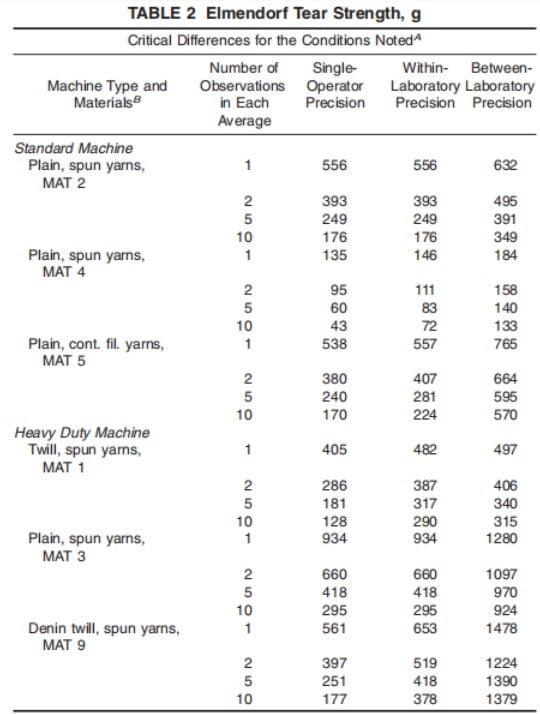
13.1 Summary – Comparing two averages, when all observations are made by the same trained operator using the same equipment and specimens are randomly selected from fabric samples, the variance should not exceed the individual operator precision values shown in Table 2 in 100 cases similar to the averages in Table 2.
13.2 Elmendorf Tear Strength, Standard Equipment, Interlaboratory Test Data – Interlaboratory testing was conducted in 1994-1995 with samples of three fabrics randomly selected for testing in each of the 11 laboratories. Eight specimens of each fabric were tested by two operators in each laboratory using Test Method D 1424. Four of the eight specimens were tested on one day and four specimens were tested on the next day. The data were analyzed using Practice D 2904 and Practice D 2906. The components of variation in Elmendorf tear strength, expressed as standard deviations, were calculated for the values listed in Table 3. The three woven fabric types are
(1) Material 2-S/1016H, 2/1 basket plain weave with spun yarn.
(2) Material 4-S/0008H, plain weave sheet, with spun yarn.
(3) Material 5-S/2438, plain weave, oxford, with spun yarn.
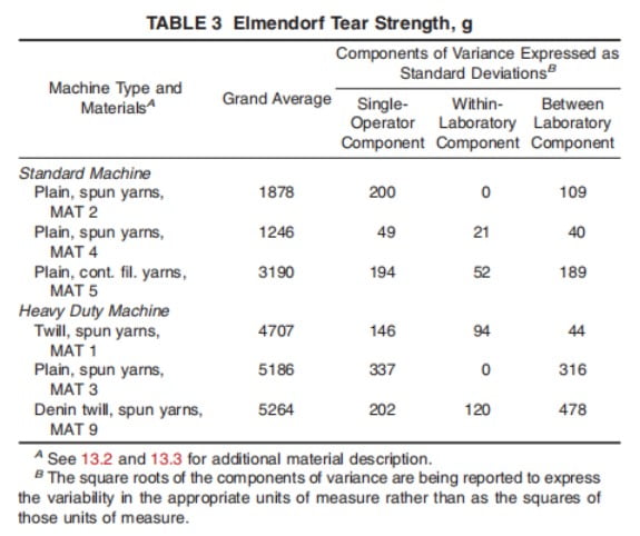
13.3 Precision – For the variance components reported in Table 3, a difference shall be considered significant at the 95% probability level if the two means of the observed values equal or exceed the critical difference in “Elmendorf” tear strength listed in Table 2. The differences related to fabric type and construction are sufficiently large to warrant separate presentation of variance components and critical differences. Therefore, no multi-fabric comparisons were performed.
Note 7: The critical variance values listed in the table should be considered as a general statement, particularly with respect to between laboratory precision. Before a meaningful statement can be made for two specific laboratories, the amount of statistical deviation, if any, between them must be determined, with each comparison based on the most recent data obtained from a batch of the fabric being evaluated so as to be as close to homogeneous as possible, and then randomly assigned to each laboratory in equal amounts.
13.4 Bias – The value of Elmendorf tear strength can only be defined using the test method. Within this limitation, test method D 1424 has no known bias.
For more information, you can click here.