
Lines are the foundation of the visual language used in engineering drawings, serving as the primary means of conveying the design, dimensions, and specifications of an object or structure. They form a universal language that engineers, manufacturers, and other stakeholders rely on to interpret and execute design intent accurately.
While many may not realize it, there are several different types of lines in engineering drawings, each with its own purpose. These lines vary in weight or width and serve specific functions in conveying the intricacies of a design. Understanding the different types of lines is crucial for effectively interpreting engineering drawings and ensuring accurate construction or manufacturing. Let’s dive into this post to learn more.
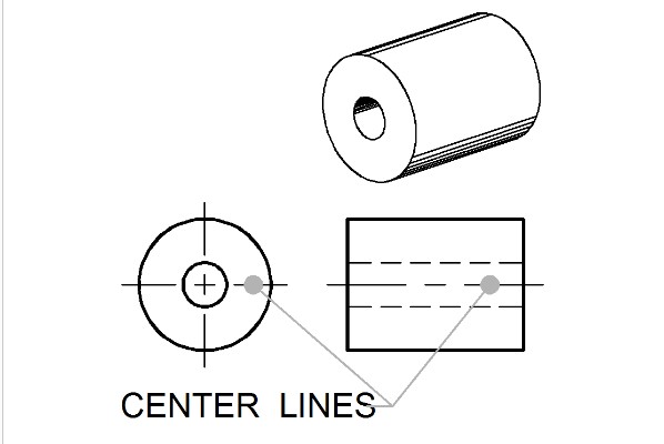
Type 1. Center Lines
Center lines, also known as axes or centerlines, are thin, long-short-long dashed lines used in engineering drawings, serving several important purposes in conveying design intent and ensuring accurate interpretation of engineering drawings. They indicate the centers of symmetrical features, such as holes, arcs, and circles, making them often used as reference points for dimensions. For example, hole diameters or center-to-center distances, are typically referenced to the centerline.
Type 2. Visible Lines
Visible lines, also known as object lines, are typically thicker than other types of lines used in engineering drawings, usually with 0.6mm thickness, making them stand out and clearly define the object’s outline. Plus, they are also solid lines, with no breaks or gaps, to ensure a continuous representation of the object’s edges. They are essential for defining the shape, size, and overall appearance of the object in the particular view being depicted, helping engineers distinguish between different features and components within the object. It can be time-consuming to draw multiple lines manually, however, many engineering CAD software programs like ZWCAD offer tools that help you quickly generate visible lines and save time.
Type 3. Hidden Lines
Hidden lines are a type of line used in engineering drawings to represent edges and contours of features that are not visible from the view of the drawing, such as holes, ribs, and cavities, that may not be visible from other views. They are important for understanding the overall shape of the object and how it fits together with other parts. Additionally, you can create them easily using structural engineering software compared to hand drawing. They are typically drawn as dashed lines with short dashes about 1/8″ long, 1/16″ gaps, and 0.3 mm thickness. This helps to distinguish them from visible lines, which are drawn as solid lines.
Type 4. Leader Lines
Leader lines are thin, solid lines with arrows drawn under an angle (usually at 30, 45, and 60 degrees) that are used in engineering drawings to connect dimensions, notes, or other annotations to specific features on the drawing. They are typically drawn in a lighter line weight than the drawing objects themselves and long enough to reach the annotation without crossing over any other lines on the drawing. This helps to ensure that the information provided is unambiguous and makes it easier for readers to understand the drawing.
Type 5. Dimension Lines
Dimension lines are essential elements in engineering drawings, conveying the exact size, location, and orientation of various objects within a design. Dimension lines are thin, solid lines with arrowheads on each end and are typically drawn in a darker shade than other lines on the drawing to make them stand out. Also, they are typically drawn parallel to the object they are dimensioning and are broken near the middle to accommodate the dimension value. This helps to ensure the accurate fabrication and assembly of components.
Type 6. Extension Lines
In engineering drawings, extension lines are thin, solid lines extending outward from an object to which a dimension refers. Typically perpendicular to the dimension line, these lines indicate the precise points where the dimension begins and ends. Furthermore, extension lines should maintain a slight distance from the object being dimensioned and avoid intersecting other extension or dimension lines, ensuring the dimensions are unambiguous.
Type 7. Section Lines
Section lines, also known as hatching, are thin, parallel lines that are used to depict the cut surface of an object in a section view. They are particularly useful when an object’s intricate internal features cannot be adequately represented in a single view. Typically drawn at an angle of 45 degrees to the object’s main axes, section lines serve as visual cues indicating the material that has been cut away. Additionally, different types of section lines are employed to represent various materials. For instance, cast iron is typically depicted with fine, closely spaced lines, while wood is represented by thicker, more widely spaced lines.
Type 8. Break Lines
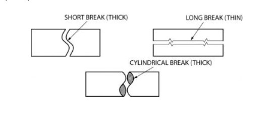
Break lines are used in engineering drawings to shorten the representation of long, uniform objects. They are usually thin, zigzag lines that indicate that a portion of the object has been omitted. This helps to save space on the drawing and makes it easier to read and understand. There are three main types of break lines:
- Long Break Lines: They are drawn with a thin, solid line typically used for long and uniform objects, such as rods, pipes, and extrusions.
- Short Break Lines: They are drawn with a thick, solid line used to indicate where an object has been broken to reveal interior features, such as holes or cavities.
- Cylindrical Break Lines: They are drawn with a smooth, wavy pattern that is specifically designed to depict the internal features of cylindrical objects, such as pipes, rods, and columns.
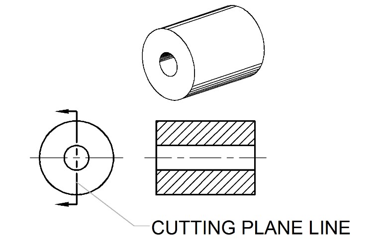
Type 9. Cutting Plane Lines
Cutting plane lines are thick, dashed lines that are used in engineering drawings to indicate where an object has been cut or sectioned to reveal its internal features. These lines, typically terminating in 90-degree arrows, serve as a visual guide for the corresponding section view, indicating the direction from which the object has been cut. This helps engineers and designers visualize the internal features of an object without having to draw a separate, detailed view of the entire object.
Type 10. Borderlines
Borderlines are thick, solid lines that are used to define the edges of a drawing or to separate different views or objects drawn on the same sheet. They are usually drawn with a thicker line weight than other drawing lines to ensure they stand out and clearly delineate the drawing area.
Conclusion
This article delves into ten types of lines commonly used in engineering drawings, exploring their specific roles in conveying critical information about the object being represented. Understanding the correct application and use of these ten essential lines is crucial for beginners to learn CAD software and create clear, concise, and informative drawings. By mastering this visual language, future engineers and designers can effectively communicate their ideas and contribute to the world of engineering innovation. Let’s share this article and let more people get helped.